If you’ve ever stared at a sensor datasheet wondering which communication protocol to wire up, you’re in good company. UART, SPI, and I2C are the three serial buses you’ll meet on almost every microcontroller, and picking the wrong one usually ends with either a rat’s nest of wiring, a bus that’s too slow, or a 2 a.m. logic-analyzer session you didn’t plan for.
This guide cuts through the vendor marketing and shows you exactly what each protocol does well, where it falls apart, and which one fits your specific project. I’ve pulled the real specs from the official NXP I2C-bus specification (UM10204) and cross-checked everything against the top-ranked articles so you don’t have to.
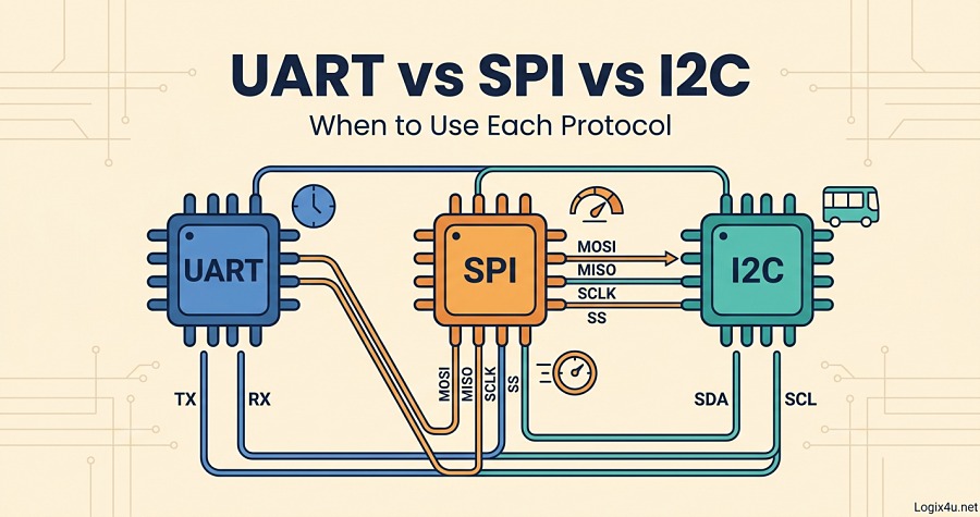
Quick Answer: UART vs SPI vs I2C in 45 Seconds
UART is a simple two-wire asynchronous link between exactly two devices, best for debug consoles, GPS, and Bluetooth modules. SPI is a fast synchronous four-wire bus that shines when you need raw throughput (SD cards, displays, ADCs) and can handle multiple slaves but eats pins. I2C is a two-wire synchronous bus with built-in addressing, ideal when you want to chain many low-speed sensors on a shared line.
Rule of thumb: Need speed? SPI. Need many devices with minimal wiring? I2C. Need the simplest point-to-point link? UART.
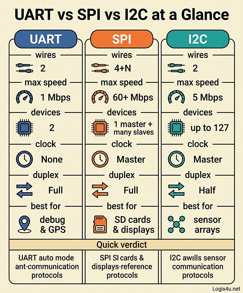
Quick-Glance Comparison Table
| Feature | UART | SPI | I2C |
|---|---|---|---|
| Full name | Universal Asynchronous Receiver-Transmitter | Serial Peripheral Interface | Inter-Integrated Circuit |
| Wires | 2 (TX, RX) | 4 + one SS per slave | 2 (SDA, SCL) |
| Clock | None (asynchronous) | Master-generated (synchronous) | Master-generated (synchronous) |
| Duplex | Full | Full | Half |
| Typical speed | Up to ~1 Mbps (commonly 9600 to 115200 bps) | Tens of Mbps (100+ MHz achievable) | 100 kbit/s to 5 Mbit/s |
| Devices supported | 2 (point-to-point) | 1 master + many slaves (limited by SS pins) | Up to 127 (7-bit) or 1023 (10-bit) |
| Addressing | None | Chip-select lines | Built-in device address |
| Pull-up resistors | No | No | Yes (required) |
| Distance | Up to ~50 ft at low baud (longer with RS-232/RS-485 drivers) | Short (same board) | Short (same board) |
| Error checking | Optional parity bit | None built-in | ACK/NACK bit |
| Best for | Debug, GPS, Bluetooth, modem-style modules | SD cards, flash, displays, fast ADCs | Sensor networks, EEPROMs, RTCs |
What Is UART and How Does It Work?
UART stands for Universal Asynchronous Receiver-Transmitter. It’s not really a “protocol” in the strictest sense but more of a hardware methodology baked into most microcontrollers. A UART converts parallel data from the CPU bus into a serial stream and sends it out on a TX (transmit) line. On the other end, another UART does the reverse on its RX (receive) line.
The “asynchronous” part is the whole point: there’s no shared clock between the two devices. Both sides agree in advance on a baud rate (9600, 19200, 38400, 57600, 115200 bps are common), and each frame is bracketed by a start bit (low) and one or two stop bits (high). An optional parity bit lets the receiver catch single-bit errors.
UART Frame Structure
Every UART byte looks like this on the wire:
- Start bit: a single low pulse that tells the receiver “new frame incoming”
- Data bits: 5 to 9 bits, usually 8, LSB first
- Parity bit (optional): even, odd, or none
- Stop bit(s): 1, 1.5, or 2 high pulses
Because there’s no clock, the two UARTs must have baud rates within roughly 2 to 3 percent of each other to sample reliably. Most references cite a 10 percent tolerance, but in practice, anything over 3 percent starts flaking out on longer frames.
Where UART Shines
- Debug consoles: printing to a serial terminal from an Arduino, ESP32, or STM32 is pure UART (usually bridged to USB through a CP2102, CH340, or FT232)
- GPS modules: almost every GPS receiver speaks NMEA over UART at 9600 or 38400 baud
- Bluetooth Classic modules (HC-05, HC-06) and GSM/LTE modems that use AT commands
- Any point-to-point link where simplicity beats speed
Where UART Falls Apart
- Only works between exactly two devices
- Slow by modern standards
- Clock drift between crystals kills long frames
- No hardware addressing, so you can’t share a bus without extra circuitry
Pro tip: If you need UART over longer cables (more than a meter or two), don’t run bare TTL levels. Add an RS-232 or RS-485 transceiver. RS-485 in particular handles hundreds of meters at reasonable baud rates, which is why it dominates industrial sensor buses.
One thing worth clearing up: UART and USART are not the same. USART (Universal Synchronous Asynchronous Receiver-Transmitter) adds an optional clock line so it can also operate synchronously. Most STM32s actually give you USARTs, but 99 percent of the time you’ll use them in UART mode.
What Is SPI and How Does It Work?
Serial Peripheral Interface, invented by Motorola in the 1980s, is the speed king of the three. It’s a synchronous, full-duplex, master-slave bus with no inherent speed ceiling in the spec. Data rates above 100 MHz are achievable on short traces, and even modest microcontrollers push SPI peripherals at 20 to 50 Mbps without breaking a sweat.
The Four SPI Lines
- MOSI (Master Out, Slave In): data flowing from master to slave
- MISO (Master In, Slave Out): data flowing from slave to master
- SCLK (Serial Clock): clock signal generated by the master
- SS or CS (Slave Select / Chip Select): one dedicated line per slave, pulled low to activate that specific device
Some devices also support 3-wire SPI (MOSI and MISO share a line) or QSPI/Quad-SPI (four data lines for flash memory), but the four-wire version is the default.
How a Transaction Works
- Master pulls the target slave’s SS line low
- Master starts toggling SCLK
- On each clock edge, master shifts one bit out on MOSI and reads one bit in on MISO (hence full-duplex: every byte you send, you also receive one back)
- When the transaction is done, master releases SS high
SPI has four modes defined by two parameters: CPOL (clock polarity) and CPHA (clock phase). They’re the single most common source of “why isn’t this chip responding” bugs. Both sides must match or you’ll get garbage.
| SPI Mode | CPOL | CPHA | Common usage |
|---|---|---|---|
| 0 | 0 | 0 | Most sensors, SD cards |
| 1 | 0 | 1 | Some ADCs, DACs |
| 2 | 1 | 0 | Uncommon |
| 3 | 1 | 1 | Some flash memory, displays |
Where SPI Shines
- SD cards and eMMC in SPI mode (QSPI in more demanding cases)
- SPI NOR flash (like Winbond W25Q series) for firmware storage
- TFT and OLED displays where frames must push fast
- High-speed ADCs, DACs, and motion sensors (MEMS accelerometers like the LSM6DSO hit 10 Mbps SPI easily)
- Radio modules like the nRF24L01 and LoRa SX127x series
- Inter-microcontroller bridges where raw throughput matters
Where SPI Falls Apart
- Pin count explodes with slave count: 3 slaves = 3+3 = 6 wires, 5 slaves = 9 wires
- No built-in error checking (no ACK/NACK, no CRC in the base spec)
- No built-in multi-master support
- Clock mode mismatches fail silently
- Signal integrity becomes a real issue on long or unterminated traces at high speed
What Is I2C and How Does It Work?
I2C (Inter-Integrated Circuit, pronounced “eye-squared-see” or “eye-two-see”) was invented by Philips Semiconductors (now NXP) in 1982. It’s the most elegant of the three when you need to chain many chips on a single pair of wires. According to the Wikipedia I2C reference, revision 7 of the official spec, released in 2021, renamed the old “master/slave” terminology to “controller/target,” though every existing chip datasheet still uses the old terms, and so does this article for clarity.
The Two I2C Lines
- SDA (Serial Data): bidirectional, open-drain
- SCL (Serial Clock): driven by the master, sometimes held low by slaves (clock stretching)
Both lines need pull-up resistors to VCC. Without them, I2C simply will not work. Typical values are 4.7 kΩ for 5V systems and 2.2 kΩ for 3.3V systems, but the right value depends on bus capacitance and speed. Lower resistors = faster rise times but more current draw.
The Four Official I2C Speeds
Straight from the NXP UM10204 specification:
| Mode | Max rate | Typical usage |
|---|---|---|
| Standard-mode | 100 kbit/s | Legacy, robust, most sensors |
| Fast-mode | 400 kbit/s | Modern sensors, most MCUs |
| Fast-mode Plus | 1 Mbit/s | Newer sensors and flash |
| High-speed mode | 3.4 Mbit/s | Rare, complex ICs |
| Ultra Fast-mode | 5 Mbit/s | Unidirectional, LED drivers |
Ultra Fast-mode is a one-way-only variant most developers never touch. Fast-mode (400 kHz) is the sweet spot for 90 percent of projects.
How a Transaction Works
- Master pulls SDA low while SCL is high → start condition
- Master sends 7 bits of address + 1 read/write bit
- Addressed slave pulls SDA low for one clock → ACK
- Data frames of 8 bits, each followed by ACK/NACK from receiver
- Master releases SDA high while SCL is high → stop condition
Clock Stretching (The I2C Superpower)
If a slave needs more time to prepare the next byte (say, an ADC that’s still sampling), it can hold SCL low even while the master is trying to clock. The master sees SCL low and waits. This is clock stretching, and it’s the reason I2C tolerates slow devices on the same bus as fast ones. It also causes 99 percent of “my I2C hangs randomly” bug reports when the master firmware doesn’t handle it correctly.
Where I2C Shines
- Sensor clusters: temperature, humidity, pressure, ambient light, IMU all on the same two pins
- Small EEPROMs (24LC256 and similar)
- Real-time clocks (DS3231, PCF8563)
- OLED displays at 128×64 resolution
- I/O expanders (PCA9555, MCP23017)
- Any project where pin count matters more than raw speed
Where I2C Falls Apart
- Half-duplex only
- Address collisions between identical chips (two BMP280 sensors both default to 0x76, and you’ll need the second on 0x77)
- Bus capacitance limits trace length and speed (a rule of thumb: 400 pF max for Fast-mode)
- Susceptible to noise on longer cables
- Clock stretching bugs bite hard
UART vs SPI vs I2C: Head-to-Head Breakdown
Speed
SPI wins by a country mile. A decent SPI peripheral pushes 20 to 60 Mbps without trying, and specialty chips hit 100+ MHz. I2C tops out at 5 Mbps in Ultra-Fast mode, but 400 kHz Fast-mode is what you’ll actually use. UART is slowest in raw throughput: even at 1 Mbps maximum, the start/stop/parity overhead eats about 20 percent of the bandwidth.
Verdict: SPI > I2C > UART.
Wiring Complexity
For a single device, UART and I2C both use 2 wires; SPI uses 4. But scale matters. For 5 slave devices:
- UART: not possible on one bus, needs 5 separate UART ports (10 wires total)
- SPI: 3 shared + 5 chip-selects = 8 wires
- I2C: still just 2 wires
Verdict: I2C wins for multi-device setups. UART wins for single-peer simplicity. SPI sits in the middle.
Power Consumption
UART is the most power-efficient because it doesn’t run a clock line and most implementations support idle-state sleep. I2C is moderate: pull-ups draw current whenever a line is pulled low, and the clock runs during transactions. SPI generally consumes the most due to the always-toggling clock during transfers and higher frequencies.
That said, for battery projects, the actual workload matters more than the protocol itself. An I2C sensor that sleeps between reads can easily beat a UART module that’s always on.
Verdict: UART > I2C > SPI for idle power. Under load, it depends on clock speed.
Number of Devices
I2C can address 127 devices with 7-bit addressing (112 usable, as some addresses are reserved) or up to 1023 with 10-bit addressing. SPI theoretically has no limit but each slave needs its own SS line. UART is stuck at 2 devices without external multiplexers.
Verdict: I2C > SPI > UART.
Distance
UART handles the longest runs, especially when paired with RS-485 transceivers (hundreds of meters at moderate baud rates). SPI and I2C are both strictly board-level protocols. Trying to run I2C over 30 cm of ribbon cable usually works. Past a meter, you’ll fight bus capacitance and need specialty buffers.
Verdict: UART > SPI ≈ I2C.
Error Detection
I2C has the ACK/NACK bit, which at least confirms a byte was received. UART has optional parity, which catches single-bit errors. SPI has nothing built in, which is why protocols layered on top of SPI (like SD card transactions) add their own CRCs.
Verdict: I2C > UART > SPI.
Complexity to Implement
UART is the simplest: two wires, a baud rate, and you’re in business. I2C has addressing, start/stop conditions, ACK bits, and clock stretching edge cases. SPI is moderately complex because of the four modes and chip-select management.
Verdict: UART < SPI < I2C (for firmware complexity).
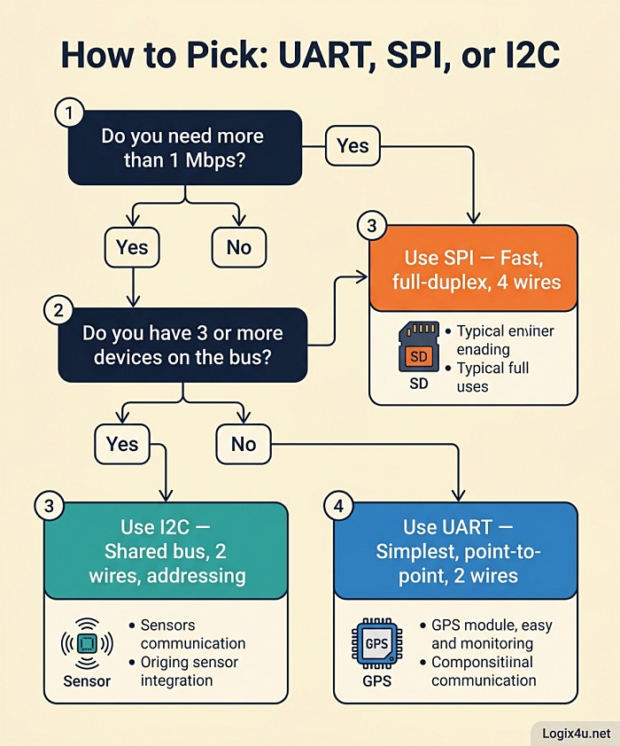
The Decision Framework: Which Protocol Should You Actually Use?
Here’s the mental model I use when starting a new embedded project.
Step 1: How many devices are on the bus?
- Exactly 2 → UART is your first choice. Simple, cheap, done.
- 3 to 8 → Either SPI or I2C. Go to Step 2.
- More than 8 → I2C. SPI’s chip-select lines will eat your GPIO budget.
Step 2: How fast do you need to go?
- Below 400 kbps → I2C. You won’t miss the speed, and the wiring is cleaner.
- 400 kbps to 1 Mbps → I2C Fast-mode Plus or SPI. Your call.
- Above 1 Mbps → SPI. It’s not even close.
Step 3: What’s your pin budget?
- Tight (an ATtiny85 or trying to fit alongside other peripherals) → I2C
- Roomy (STM32, ESP32 with pins to spare) → SPI or a mix
Step 4: How long are the traces?
- Same PCB, under 30 cm → any of the three
- Short cable, under 1 m → UART or I2C (with stronger pull-ups)
- Longer cable or off-board → UART with RS-232/RS-485 transceivers
Step 5: Does your chip leave you a choice?
Plenty of sensors and modules only speak one language. A BME280 can do either I2C or SPI (switch by pin). A GPS module is UART-only. An SD card is SPI-only in hobbyist land. Read the datasheet first.
Real-World Scenarios: Which Protocol Wins?
Scenario 1: Weather Station on an Arduino Uno
You want temperature, humidity, pressure, a real-time clock, and an OLED. That’s 5 devices, all low-bandwidth, on an ATmega328P with limited GPIO.
Winner: I2C. All five devices exist as I2C parts. You’ll use 2 pins total (A4/A5 on the Uno), and you’ll still have the rest of the board free for a relay, a buzzer, and whatever else.
Scenario 2: Data Logger with SD Card and High-Rate Accelerometer
You need to sample a MEMS accelerometer at 1 kHz and log to SD. That’s a continuous write pipeline of tens of kilobytes per second.
Winner: SPI. SD cards in SPI mode hit several Mbps. The accelerometer over SPI gets you deterministic timing. I2C would bottleneck the logger.
Scenario 3: ESP32 Talking to a GPS Module and a PC
A navigation prototype needs GPS data coming in and debug output going out to a USB terminal.
Winner: UART (twice). GPS is UART-native. USB debug is UART bridged through a USB-to-serial chip. The ESP32 has three hardware UARTs, which is plenty.
Scenario 4: 16-Channel Relay Board
You need to control 16 relays from a microcontroller with few spare pins.
Winner: I2C with I/O expanders. Two MCP23017 chips on I2C give you 32 I/O pins using just 2 wires. SPI shift registers (74HC595) would work too, but I2C is cleaner and you can read state back without extra logic.
Scenario 5: High-Resolution TFT Display for a Game
A 320×240 color display needs fast refresh for anything animated.
Winner: SPI. TFT controllers like the ILI9341 run 20 to 40 MHz SPI and push full-frame updates in under 100 ms. I2C would manage maybe 1 frame per second. UART isn’t even in the conversation.
Mixing UART, SPI, and I2C in the Same Project
Here’s something competitor articles skip: you almost never pick just one. A real embedded project uses all three. A drone flight controller has:
- UART for telemetry radio and GPS
- SPI for the IMU (fast, deterministic)
- I2C for the magnetometer, barometer, and battery monitor
Modern microcontrollers like the STM32F4, ESP32, and RP2040 have multiple peripherals of each type on dedicated hardware blocks, so using three buses at once costs almost nothing in CPU load. The only thing to watch is shared pin functions. Plan your pinout before soldering.
Common Pitfalls and How to Fix Them
UART Pitfalls
- Garbled text in terminal → baud rate mismatch. Double-check both sides match exactly (9600 vs 9608 will both “work” but drop bytes randomly).
- TX and RX swapped → you crossed them when you should have crossed them only once. Device A’s TX goes to Device B’s RX and vice versa.
- No 3.3V/5V level shifting → frying a 3.3V ESP32 UART pin with a 5V Arduino TX line. Use a level shifter.
SPI Pitfalls
- Silent failure, nothing on MISO → usually a CPOL/CPHA mismatch. Try all four modes.
- Slave ignored → SS line not pulled low, or wrong SS pin selected. Logic analyzer is your friend.
- Corrupt data at high speed → signal integrity. Shorten traces, add a series resistor (22 to 47 Ω) on SCLK, or drop the clock rate.
I2C Pitfalls
- Address collision → two devices with the same default address. Check datasheets; most have a hardware address pin.
- SDA stuck low → a slave crashed mid-transaction. Power cycle or toggle SCL manually to force a stop.
- Intermittent “NACK received” → pull-ups too weak, bus capacitance too high, or clock stretching not handled. Try 2.2 kΩ pull-ups and a lower clock rate first.
- Works on bench, fails in enclosure → EMI coupling onto SDA/SCL. Shielded cable or move I2C traces away from switching regulators.
Microcontroller Support at a Glance
| MCU / Board | UART ports | SPI ports | I2C ports |
|---|---|---|---|
| Arduino Uno (ATmega328P) | 1 hardware + software serial | 1 | 1 |
| Arduino Mega 2560 | 4 hardware | 1 | 1 |
| ESP32 | 3 hardware | 4 (2 usable) | 2 |
| STM32F103C8 “Blue Pill” | 3 USART | 2 | 2 |
| Raspberry Pi Pico (RP2040) | 2 | 2 | 2 |
| Raspberry Pi 5 | 5 (via config) | 2 | 2 |
Most of these support additional software-bit-banged versions if the hardware peripherals run out, though performance drops.
When to Reach for Something Else Entirely
If none of these three fit your needs, a few neighbors worth knowing:
- CAN bus: rugged, differential, up to 1 Mbps classic or 8 Mbps CAN-FD, standard in automotive
- RS-485: UART wrapped in a differential transceiver, 32+ nodes, hundreds of meters
- USB: when you need PC connectivity and high bandwidth
- Ethernet / TCP-IP: when going off-board and needing real networking
- 1-Wire: Dallas/Maxim’s single-signal bus for temperature sensors (DS18B20 fame)
Pro Tips From the Trenches
- Buy a cheap logic analyzer. A $15 Saleae clone plus Sigrok or PulseView will save you hours on every new bus bring-up.
- Always add test points to SDA, SCL, MOSI, MISO, SCLK, and SS during prototyping.
- Read the datasheet timing diagrams before wiring. “Works” and “works reliably over temperature” are different things.
- I2C pull-up values matter more than you think. Start at 4.7 kΩ, measure rise time on a scope, halve the resistor if you see slow rises.
- SPI mode mismatches fail silently. If a new slave doesn’t respond, cycle through modes 0-3 before blaming wiring.
- Don’t bit-bang unless you have to. Hardware peripherals are faster, more reliable, and free up CPU for real work.
Frequently Asked Questions
Which is faster: UART, SPI, or I2C?
SPI is by far the fastest, routinely hitting 10 to 60 Mbps and capable of 100+ MHz in specialized chips. I2C reaches 3.4 Mbps in High-speed mode and 5 Mbps in Ultra Fast-mode but is normally used at 100 or 400 kHz. UART is the slowest, typically 9600 to 115200 bps, with some peripherals stretching to 1 Mbps.
Can I use SPI, I2C, and UART together in one project?
Yes, and most real projects do. Modern microcontrollers have dedicated hardware peripherals for each, so running all three simultaneously costs almost no CPU overhead. A typical setup: UART for GPS, SPI for an SD card, I2C for sensors.
Can UART communicate with multiple devices?
Not natively. UART is strictly point-to-point. You can use a UART multiplexer, an RS-485 transceiver with a custom addressing protocol, or software-defined “networks” like Modbus RTU to connect multiple devices, but all of those add complexity.
Why does I2C need pull-up resistors but SPI and UART don’t?
I2C lines are open-drain, meaning devices can only actively pull the line low. Something has to pull it back high, and that’s the pull-up resistor’s job. SPI and UART use push-pull outputs that actively drive both states, so no external pull-ups are needed.
What’s the difference between UART and USART?
UART supports only asynchronous communication (no clock signal). USART adds an optional synchronous mode with a clock line. Most STM32 MCUs have USART peripherals but use them in async (UART) mode 99 percent of the time. Functionally, if you’re not using the clock, UART and USART are identical.
How long can I2C cables be?
The practical limit is about 1 meter for reliable communication at 100 kHz, and less for 400 kHz. The total bus capacitance must stay under 400 pF for Fast-mode. For longer runs, use I2C buffers like the PCA9517 or switch to differential protocols.
What does “master/slave” mean in I2C and SPI?
The master device controls the clock and initiates all transactions. Slaves only respond when addressed. As of 2021, the official I2C spec (NXP UM10204 Rev. 7) replaced these terms with “controller” and “target,” but the old terminology is still used in almost every datasheet and tutorial.
Which protocol uses the fewest pins for many devices?
I2C, hands down. Any number of devices share the same 2 pins (SDA and SCL). SPI needs one extra chip-select pin per slave, and UART needs a dedicated pair per device.
Is SPI or I2C better for reading a sensor at high speed?
SPI. For anything above 400 kHz sample rates, the I2C overhead of start conditions, addresses, and ACK bits eats into your effective throughput. SPI streams data continuously with minimal overhead.
Can I mix 3.3V and 5V devices on I2C?
Yes, with care. Use a level-shifter IC like the PCA9306 or a simple MOSFET level shifter. Don’t just tie the lines together: the 5V pull-up will push current into a 3.3V pin and eventually kill it.
Final Verdict
No single protocol is best. They’re tools, and choosing between them is a matter of matching the tool to the job:
- Pick UART when you need the simplest possible link between two devices, or when your peripheral only supports UART (GPS, Bluetooth modems, debug consoles)
- Pick SPI when you need raw speed, tight timing, or are working with SD cards, flash memory, fast ADCs, or graphical displays
- Pick I2C when pin count matters, you’re connecting many slower peripherals, or you want to keep wiring dead simple as you scale
Bookmark this page: most engineers I know end up revisiting the same decision every year or two. And if you’re building something with all three (most real projects use all three), the earlier you plan your bus layout, the fewer headaches you’ll hit at bring-up.